Field Telephones
I’m no field telephone fanatic, but I’ve been at least a bit interested since Chaosvermittlung starting fiddling around with that kind of gear at Chaos Events.
One thing that kind of surprised me though was that there seems to be little information on how to actually build your own gear. So I wanted to dive into that a little bit.
Schematics
Now if you’ve looked at a few field telephones, you’ll see that they usually have some kind of schematic on there, at least older models. That’s somewhat neat, but a lot of times, they are not specific enough or contain somewhat hard to get parts. So they may serve as more of a reference or better: inspiration, than an actual building plan on how to make your own field telephone
DIY Field Telephone
I don’t want to start completely from scratch, for now at least. Here are some thoughts:
- Use a regular phone handset. They are easily available, and almost always use a 4p4c (RJ9 or RJ10?) connector. I found this pinout, but I’m not sure if it’s generally applicable. Also, they used to use carbon microphones, like most field telephones, but newer models would use electret microphones instead. Let’s see if we can make that happen.
- There are some pictures in Wikimedia Commons, however no schematics
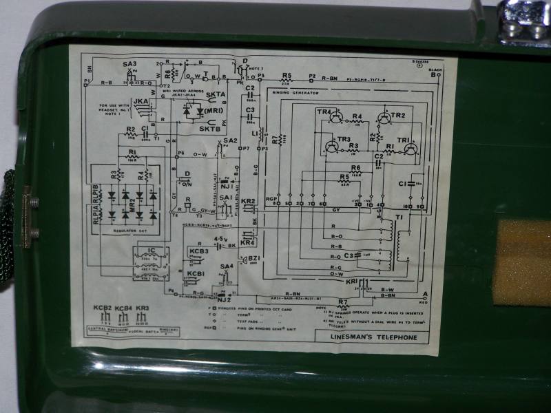
- Use an electronic ring voltage generator instead of a handcranked generator. This just seems the more accessible way today. There are some newer field telephones out there doing the same thing, like the “BW Amtstelefon Krone WF” (probably, could not find any schematics) or the PYE/TMC Linesmen’s telephone 1705 (schematic via greenradio.de, more details, another schematic)
Maybe useful schematics:
- TP-25
- F.Tf.-50
- FF OB/ZB
- Example via https://www.ar15.com/forums/outdoors/Homebrew_Field_Telephone__Updated_/17-642825/
The transformer
I wasn’t sure what the transformer in the cicuits would be used for. Thankfully, @lpbkdotnet@mstdn.social was able to provide some insight,and also solved some other mysteries (Mastodon Thread)
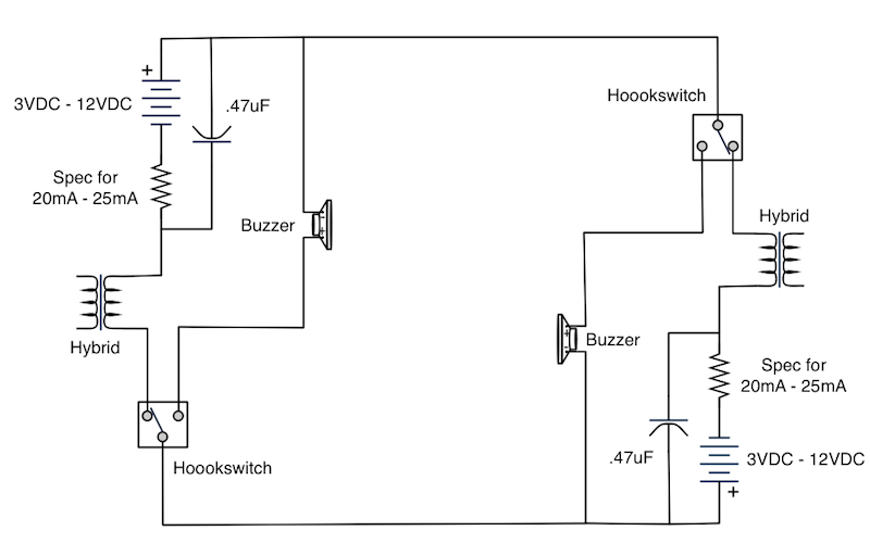
the transformer is an “anti sidetone induction coil” or astic which limits the amount you can hear yourself in the handset It can also improve the impedance match to the line, for better transmission efficiency over long distances. Transformers are expensive though, so this design uses a cheap potential divider to limit the sidetone instead These were cheap phones sold for use on private systems and don’t work well on long cable runs, but work fine up to a few hundred meters! it’s been a while since I played with one (and different militaries may have done different things), but I think the PTT button probably only affects the mic? Sidetone may still be present, as it reassures you that the thing is on and working, though that may just be a secondary effect and driving 3km of wire might be more important? It’s sometimes tough to reverse engineer a “why” when a simple series circuit of a carbon mic, a battery, and a receiver will work with no extras! I dredged up a diagram for a British F Type and it doesn’t have a PTT The German FF33 does though, but there isn’t anything in the circuit that’s inherently simplex - it looks like the PTT button is mostly to disconnect the local battery when you’re not transmitting - presumably to make the battery last longer? The British F type combines the astic with the buzzer, which is a neat trick!
Further references about anti-sidetone circuitry:
- Some Principles of Anti-Side-Tone Telephone Circuits(H. J. C. SPENCER, 1956) [local mirror]
- The Anti-Sidetone Station Circuit, by J. W. FOLEY [local mirror]
- Antiside Tone Circuit
- TECHNICAL MANUAL - COMMON-BATTERY TELEPHONE EQUIPMENT (September 3, 1942) [local mirror]
- A.L. Albert - Electrical Communication - Antisidetone Circuits
Notes
- Sometimes they’re also called “Hybrid”
- Telephone line audio interface circuits
- Covers a lot of topics around all of this
- https://mysite.du.edu/~etuttle/electron/elect61.htm
Seems like one could get something usable done with a 600Ohm Center Tapped transformer: http://cast.bada24.net/spboard/board.cgi?id=study&action=simple_view&gul=13 Which should be somewhat possible to get:
- Triad TY-304P (Datasheet) or TY-401P
Ringing Circuit
First try with a transistor only astable multivibrator using this as my main reference failed, likely due to my lack of electronics skills.
Second try was using a 555 timer to create the same thing, following this circuit, but using BD237 and 238 transistors instead becaus that’s what I had on hand. First time building this ciruit worked so far; I was missing the proper inductor for L1 as well as a matching transformer. But we got a stable square wave with the parameters I was looking for. Next up would be to get the missing parts, and then connect it to a proper field telephone to see if we can make it ring. This page gets a little deeper into biasing of the transistors, which I know nothing about, but might be interesting to further optimize this later down the road.
Run number 3 was kind of successful, using this circuit via Telephone Circuits 
- We got a ring on a more modern phone with dedicated power supply, but not on our “old” normal phone.
- Output voltage after transformer was 58V peak-to-peak, so about 21V AC, (conversion factor 2.828) which is not enough. With the ringer phone, it breaks down to about 7V AC
- Feedback on mastodon was that it may be caused by a too small transformer.
- Original transformer in the schematic is a “273-1365” by Radio Shack. Details: 12VAC 450ma from 120VAC Input
- We used Printtrafo, 0,35 VA, 24 V, 14,6 mA, RM 15 mm
- Probably need something bigger, like 10 VA, 24 V, 416 mA, RM 27,5 mm
- Question is whether Factor ~10 is enough in this case
- Feedback on mastodon was that it may be caused by a too small transformer.
More references
- Linesman’s Telephone Field version 1705 circuit
- Making phones ring on a closed circuit / intercom system - PDF Mirror
- Telephone ringing circuits - includes quite good descriptions of ringing signals etc
- Understanding Telephones
- Generating Rings @ hackaday.io
Headset Circuit
Need an RJ10 to breadboard adapter, which are a bit hard to come by. There are some you can buy from eLabGuy, e.g. this one, but this isn’t all that trustworthy. Instead, I found two designs on OSHpark, one with some supporting PCB around it, and one pretty barebones. Will need to find the proper connectors and figure out which one is more suitable
Next Steps
Build some prototypes
- Get a regular field telephone
- Connect it all together and hope it works somehow 😅
Phone adapter
Thinking about this further, maybe we might even be able to build some sort of adapter where you could just plugin a regular phone, and use it as a field telephone? It could add the following things:
- A ring generator
- Some sort of power supply for microphone amplification
So in its simplest form something like this:
                                             ┌───────┐
        O───────┬─────────────┐       ┌──────┤Battery├──────┐
                │             │       │      └───────┘      │
           ┌────┴────┐      ┌─┴───────┴─┐                 ┌─┴───┐       ┌──────┐
  Field    │  Ring   │      │    1:1    │                 │Phone├───────┤Phone │
Telephone  │Generator│      │Transformer│                 │Jack │       │      │
  Line     └────┬────┘      └─┬───────┬─┘                 └─┬───┘       └──────┘
                │             │       │                     │
        O───────┴─────────────┘       └─────────────────────┘
Exchange
When you build the phone, you might as well build an exchange as well.. But that’s for the future I suppose.
Supporting gear
Might be useful as a reference
Buyable bits
- RJ11 Male to 2*Alligator Clips Test Cord, 1.5M
- Double 3.5mm Audio Jack Female to Male RJ9 Plug Converter
Link collection, further references
- All kinds of field telephones, e.g. the FF 33
- Details on the British Telephone Set F. Mk. II.
- Type F Field Telephone
- 2 Feldtelefone - Identifikation und zum laufen bringen